Salut Pascal,
Voici qq notes sur les pompes perméates...
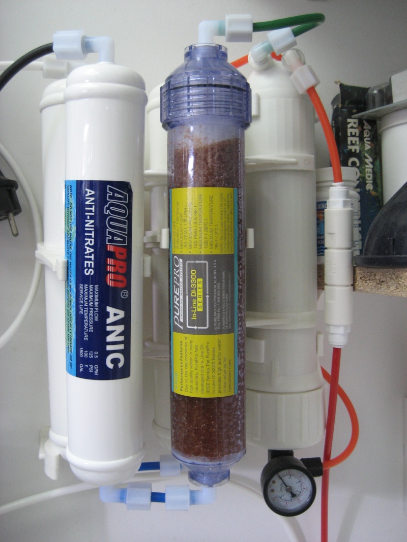
AQUATEC Permeate Pump Installation Instructions
1. Mounting of Permeate Pump: We include Part Number 25-021 Permeate Mounting Clip Kit, (includes clip and 2 #10 x 3/4" self tapping screws). Mount the clip on the RO systems bracket or other suitable location using the two screws provided. We also provide the optional Quick Connect fittings already installed into the pump. Remove and discard the blue insert protectors that are inserted into the quick connect fittings.
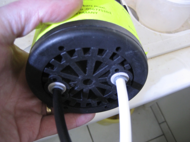
2. The label clearly shows the location of each port. Mount the Permeate Pump with Outlets (both brine and permeate) positioned up. This step is VERY IMPORTANT to rid any entrapped air.
3. Shut off feed water and turn off product tank valve. Bleed residual pressure by opening the faucet.
4. Locate the "BRINE TO DRAIN" tube. it is extremely important that the flow restrictor is in front of (before) the "brine inlet" to the Permeate Pump. The pump will not operate if the restrictor is in the "BRINE OUT" line leading to the drain.
a. Insert tube firmly into "BRINE IN" fitting on the Permeate Pump. Be sure tube bottoms out in the fitting.
b. Connect a new length (long enough to reach the air gap drain) of tubing to the "BRINE OUT"
fitting on the Permeate Pump. Be sure tube bottoms out in the fitting. This tube connects directly to the air gap drain.
5. Locate the product water (permeate) tube exiting (after) the membrane leading to the inlet side of the hydraulic shut-off valve. The outlet tube from the hydraulic shut-off valve leads to the TEE on the inlet side of the post-filter which leads to the product water tank and the product delivery faucet as shown in Figure 4.
a. Disconnect the tube from the inlet side of the hydraulic shut-off valve and connect the tube to the "PERMEATE IN" fitting on the Permeate Pump. Be sure the tube bottoms out on the fitting.
b. Connect a new tube from the "PERMEATE OUT" fitting on the Permeate Pump to the inlet side of the hydraulic shut-off valve as shown in Figure 5. Be sure the tube bottoms out on the fitting. If it is desired not to use the hydraulic shut-off valve, connect the permeate pump as shown in Figure 6 (see installation notes).
6. Turn on feed water supply and open product tank valve. The Permeate Pump should begin cycling. An audible clicking sound will be heard as the pump operates. Be sure to point this out to your customer so that he understands that this is normal. This will avoid a service call later. Important: If pump is not cycling (clicking), make sure all connections are made correctly and that all entrapped air has been bled from the lines by just cracking open the faucet.
Note: The attached specification sheet shows a typical R.O. system diagram for reference. If you want to retrofit another type of R.O. unit (a manifold type) or if your system has another configuration of hydraulic shut-off valve, or if you are using an electric booster pump, consult factory for instruction.
Technical Specifications (dimensions are in inches}
FIGURE 1. PERMEATE PUMP DIMENSIONS
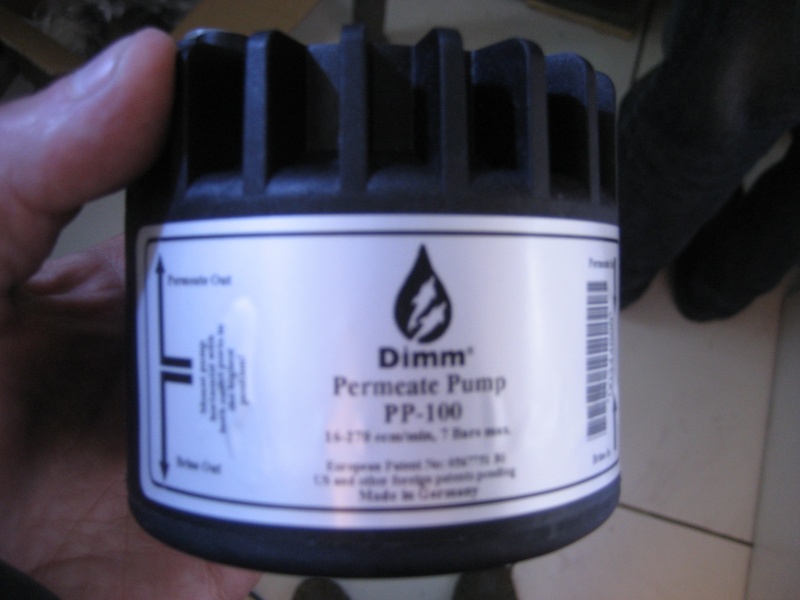
Aquatec permeate pump saves water
Installation Notes
The hydraulic shut off valve may be removed from the system and the Permeate Pump will operate as the shut off valve. This configuration may be used only if a substantial volume of water is drawn from the tank each time. The benefit is that the system will produce more water than with the shut off valve installed. If however, the amount of water withdrawn is small (a cup at a time), it is recommended that the hydraulic shut off valve be retained as shown in Figure 5. This will reduce TDS creep of the RO membrane. The addition of the Permeate Pump decreases the time to fill the tank, but it does not reduce the amount of water produced. For manifold type RO systems, contact the factory for installation recommendations.
Technical Specifications
Part number ERP 1000
Pump Type Positive displacement, reciprocating, single action diaphragm, hydraulically driven
Weight 1 Ib.
Materials Wetted Materials: NSF listed and FDA approved thermoplastic; EPDM
Fittings Optional Jaco or John Guest Fittings, straight or elbow quick disconnect. We ship with the John Guest fittings already installed.
Mounting Always mount with outlet ports up. Mounting clip (AB5) with (2) #105.5. screws available
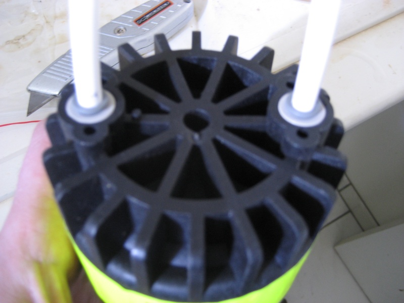
Retrofit Mounting Order membrane clip if required (Figure 3). Base of Membrane clip attaches to base of Permeate Pump clip with supplied fastener. Permeate Pump can then be mounted to membrane with clip assembly as shown in Figures 5 & 6.
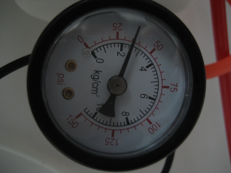
Hydraulic Maximum Pressure -100 psi brine and 100 psi permeate side
Environmental 0- ~100% humidity, 32 -140 degrees F ambient; water temp, 32- 140 degrees F
Warranty 2 years
Aquatec permeate pump saves water
Figure 3. Permeate Pump Clip
Aquatec ERP-1000 Permeate Pump
Pour voir les schéma, allez ici : http://www.waterfiltersonline.com/permeate-pump-installation.asp
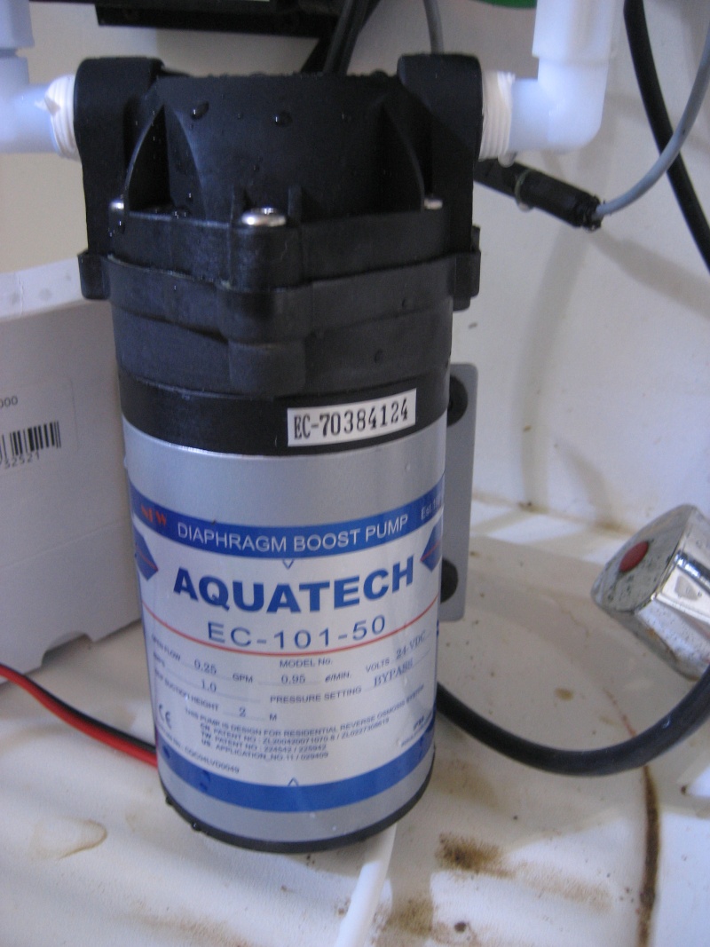
La pompe booster est là pour les problèmes de pression ou de rendement. En théorie, elle ne devrait pas ou peu jouer sur la quantité de rejet.
Si je me rappelle bien Pascal, on avait commandé notre osmoseur chez ET la dernière fois et cela date de 1 an ou 1 an et demi. Moi, ma membrane est HS. Comment est la tienne ?
J'avais également un rendement supérieur à 1 et ceci sans pompe booster.
Le problème est que cet osmoseur 100 gallons (380 litres) / jour avait un restricteur non adapté. C'était un restricteur de 50 gallons !! Ceci explique le taux de rejet faible de l'osmoseur en regard de l'eau osmosée produite.
C'est sûr, on a économisé de l'eau mais on a flingué la mlembrane en 1 an au lieu de 3 ou 5

Stéphane.
(PS : peutêtre peut-on élargir le sujet à la section eau douce pour avoir plus de retour d'expérience ?)


 .
.